Reading Time: 16 mins

Ever watched a robot zoom around a track all by itself and wondered how it works? That’s the magic of a line follower robot—and you can build one yourself, even if you’ve never touched a circuit board before.
The Problem: Most robotics tutorials throw complex jargon at beginners, making a simple project feel overwhelming. Kids and parents want to learn robotics but don’t know where to start.
Why It Matters: Without accessible entry points, young learners miss out on developing critical STEM skills early. Studies show that hands-on robotics projects significantly boost problem-solving abilities and computational thinking in children.
The Solution: This guide breaks down line follower robot construction into simple, actionable steps. You’ll understand exactly how sensors detect lines, how motors respond, and how to program your robot—all explained clearly. By the end, you’ll have a working robot and the confidence to tackle more advanced projects.
At ItsMyBot, we’ve seen thousands of students light up when their first robot successfully follows a path. That moment when technology clicks? It’s unforgettable. Let’s make it happen for you.
What You’ll Learn:
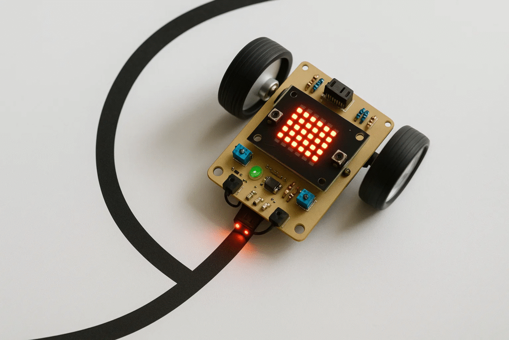
Before diving into construction, let’s understand what makes these robots tick. A line follower robot is an autonomous vehicle that detects and follows a specific path—usually a black line on a white surface or vice versa.
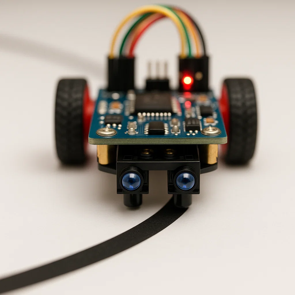
The secret lies in light reflection. Dark surfaces absorb light while light surfaces reflect it. Line sensors measure this reflected light to determine whether they’re over the line or off it. When the sensor detects the dark line, it sends a signal to the microcontroller, which then adjusts the motors to keep the robot on track.
Think of it like walking on a tightrope—your eyes constantly check your position and your body makes tiny adjustments to stay balanced. Your robot does the same thing, just much faster.
Line follower robots aren’t just fun projects—they’re simplified versions of technology used in:
Understanding line followers gives you foundational knowledge for advanced robotics and automation systems. This makes it an excellent introduction to robotics for kids who want to explore STEM careers.
Building a line follower robot requires specific components that work together seamlessly. Here’s everything you need and why each part matters.
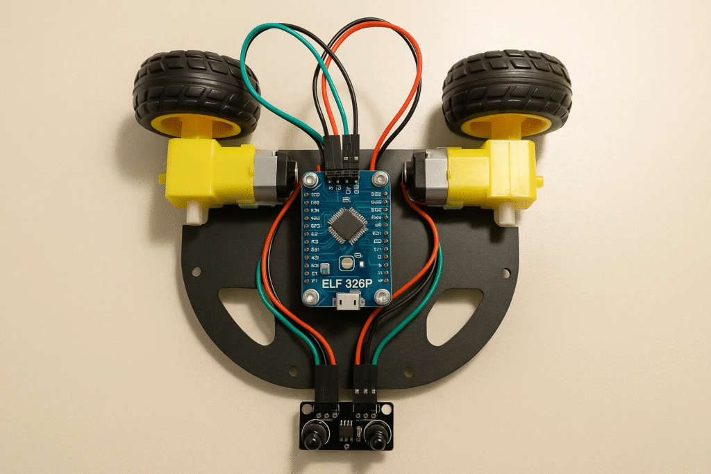
Microcontroller: ELF 328P Mainboard This is your robot’s brain. The ELF 328P processes sensor inputs and controls motor outputs. It’s beginner-friendly, compatible with popular programming environments, and powerful enough for complex behaviors as you advance.
Line Sensors (IR Sensors) These infrared sensors detect the line your robot follows. Most beginners start with 2-3 sensors, though advanced robots use 5 or more for smoother tracking. The sensors emit infrared light and measure how much bounces back—less reflection means a dark line.
DC Motors (2 pieces) These drive your robot’s wheels. Two motors allow differential steering—by running motors at different speeds, your robot can turn without additional steering mechanisms.
Motor Driver Motors need more power than microcontrollers can provide directly. The motor driver acts as a bridge, letting your microcontroller control high-power motors safely.
Chassis and Wheels Your robot needs a sturdy body. Educational kits typically include pre-designed chassis with mounting points for all components. Wheels should match your motors and provide good traction.
Power Source A power bank or battery pack (typically 3.7V-7.4V) keeps everything running. Make sure it can supply enough current for your motors and electronics simultaneously.
Additional Components Included:
Want to take your project further? Consider adding:
These additions transform a basic line follower into a smart car capable of autonomous navigation. Many students who master line followers move on to creating robotics projects that inspire learning through fun.
You have three options:
For beginners, we strongly recommend complete kits. They save time, prevent compatibility headaches, and include everything needed without overwhelming choices.
Now comes the exciting part—putting everything together. Follow these steps carefully, and you’ll have a working robot in no time.
Before touching any components:
Pro tip: Keep small components in a container so nothing gets lost. Screws and sensors have a talent for disappearing.
Start with your robot’s body:
The chassis forms your robot’s foundation. A wobbly chassis leads to unreliable movement, so take your time here.
Sensor placement is critical for performance:
Connect sensor wires to the designated pins on your ELF 328P mainboard. Different colored wires typically indicate:
Double-check connections before powering on. Reversed polarity can damage sensitive electronics.
Now for the brain and muscle:
Organized wiring prevents troubleshooting nightmares later. Use cable ties to keep wires neat and away from moving parts like wheels.
Your robot needs juice:
Safety note: Always disconnect power when making circuit changes. This protects both you and your components.

Do a final check:
Your robot should look neat and purposeful, not like a wire explosion. A well-organized robot is easier to program and troubleshoot.
Hardware complete? Awesome. Now let’s bring your robot to life with code. Don’t worry if you’ve never programmed before—we’ll start simple.
Before writing code, understand what your robot needs to do:
Basic Logic Flow:
This simple loop happens dozens of times per second, creating smooth line following.
The ELF 328P mainboard typically works with Arduino-style programming:
Many educational kits include custom programming software with visual block coding interfaces, making it even easier for beginners.
Here’s a simple program to get you started:
// Define pin connections
int leftSensor = 2;    // Left line sensor
int rightSensor = 3;   // Right line sensor
int leftMotor = 9;     // Left motor control
int rightMotor = 10;   // Right motor control

void setup() {
  // Initialize pins
  pinMode(leftSensor, INPUT);
  pinMode(rightSensor, INPUT);
  pinMode(leftMotor, OUTPUT);
  pinMode(rightMotor, OUTPUT);
}

void loop() {
  // Read sensor values (LOW = black line detected)
  int leftValue = digitalRead(leftSensor);
  int rightValue = digitalRead(rightSensor);

  // Decision making
  if (leftValue == LOW && rightValue == LOW) {
    // Both sensors on line - go straight
    moveForward();
  }
  else if (leftValue == LOW && rightValue == HIGH) {
    // Left sensor on line - turn left
    turnLeft();
  }
  else if (leftValue == HIGH && rightValue == LOW) {
    // Right sensor on line - turn right
    turnRight();
  }
  else {
    // No line detected - stop
    stopMotors();
  }
}

// Motor control functions
void moveForward() {
  digitalWrite(leftMotor, HIGH);
  digitalWrite(rightMotor, HIGH);
}

void turnLeft() {
  digitalWrite(leftMotor, LOW);
  digitalWrite(rightMotor, HIGH);
}

void turnRight() {
  digitalWrite(leftMotor, HIGH);
  digitalWrite(rightMotor, LOW);
}

void stopMotors() {
  digitalWrite(leftMotor, LOW);
  digitalWrite(rightMotor, LOW);
}
Let’s break down what’s happening:
Setup Section: Runs once when the robot powers on. It tells the microcontroller which pins connect to sensors (inputs) and motors (outputs).
Loop Section: Runs continuously. It reads sensors, makes decisions based on those readings, and controls motors accordingly.
Motor Functions: These helper functions make the code cleaner and easier to modify. Instead of writing motor control code repeatedly, we just call moveForward() or turnLeft().
First test tip: Start with a simple straight line before trying curves. This helps verify basic functionality.
Inverted sensor logic: If your robot runs away from the line, your sensor values might be inverted. Try changing LOW to HIGH and vice versa in your code.
Motor directions reversed: If left/right are backwards, swap your motor pin assignments or your turn functions.
Too fast/too slow: This simple code runs motors at full speed. You might need PWM (pulse width modulation) for speed control on complex tracks.
For students interested in diving deeper into programming logic, exploring Python programming concepts provides excellent foundations applicable to robotics.

Your robot needs a path to follow. Creating the right track makes the difference between frustration and success.
Line Specifications:
Track Complexity: Start simple and gradually increase difficulty:
Materials needed:
Construction steps:
Pro tips:
Once your basic code works, challenge your robot with:
Figure-8 pattern: Tests both left and right turning equally
Spiral: Progressively tighter curves test turning precision
Grid pattern: Multiple 90-degree turns in sequence
Speed track: Long straightaways with gentle curves
Each track type reveals different aspects of your robot’s performance and helps you refine your code. Students who master track design often develop skills applicable to programming robots more generally.
Even experienced builders encounter problems. Here’s how to fix the most common issues quickly.
Possible causes:
Solutions:
Possible causes:
Solutions:
Possible causes:
Solutions:
Possible causes:
Solutions:
Use Serial Monitoring: Add these lines to your code to see what sensors detect:
Serial.begin(9600);  // Add to setup()
Serial.print("Left: ");
Serial.print(leftValue);
Serial.print(" Right: ");
Serial.println(rightValue);  // Add to loop()
Open the Serial Monitor in Arduino IDE to watch real-time sensor values. This reveals exactly what your robot “sees.”
Test Components Individually: Don’t troubleshoot everything at once. Test sensors separately, then motors, then combined behavior.
Document Changes: Write down what you tried and the results. This prevents repeating failed solutions and helps track progress.
Basic line following mastered? Time to level up with these enhancements.
Instead of just ON/OFF, control motor speed for smoother movement:
int leftSpeed = 150;   // Speed value 0-255
int rightSpeed = 150;

void moveForward() {
  analogWrite(leftMotor, leftSpeed);
  analogWrite(rightMotor, rightSpeed);
}

void turnLeft() {
  analogWrite(leftMotor, leftSpeed * 0.5);  // Slow left wheel
  analogWrite(rightMotor, rightSpeed);       // Full right wheel
}
PWM (Pulse Width Modulation) gives you 256 speed levels instead of just two. This creates gentler turns and more precise control.
PID (Proportional-Integral-Derivative) control makes following smoother on curves:
Basic concept: Instead of simple on/off decisions, calculate how far off-center you are and adjust proportionally.
float Kp = 1.0;  // Proportional constant
int error = leftValue - rightValue;
int correction = Kp * error;

analogWrite(leftMotor, baseSpeed + correction);
analogWrite(rightMotor, baseSpeed - correction);
This advanced technique keeps your robot centered on the line rather than zigzagging. It’s the same control method used in industrial automation and artificial intelligence in robotics.
More sensors mean better detection:
5-Sensor Configuration:
With five sensors, you can implement more sophisticated logic:
Add an ultrasonic sensor to avoid collisions:
int distance = getDistance();  // Custom function to read ultrasonic

if (distance < 10) {
  stopMotors();
  delay(500);
  // Backup or navigate around obstacle
}
This transforms your line follower into an autonomous vehicle that handles unexpected obstacles.
Include a remote control for manual intervention:
Many educational kits include infrared remotes perfect for this purpose.
Make your robot interactive:
Buzzer feedback:
LED display:
These features make demonstrations more engaging and help with troubleshooting. They’re especially popular in coding classes for kids where visual feedback enhances learning.
Building a line follower teaches more than just robotics—it develops fundamental skills applicable across STEM fields.
Electronics Basics:
Programming Fundamentals:
Engineering Thinking:
Physics Applications:
Once you’ve mastered line following, explore these projects:
Beginner-Intermediate:
Intermediate-Advanced:
Advanced:
Many students who start with line followers progress to STEM careers in robotics, engineering, and computer science.
Learning accelerates when you connect with others:
Online communities:
Local opportunities:
Competition options:
Sharing your project online, entering competitions, or teaching others reinforces your learning and opens doors to advanced opportunities.
How long does it take to build a line follower robot?
With all components ready, expect 2-4 hours for assembly and basic programming. First-timers might need 6-8 hours including learning time. Testing and optimization add several more hours as you refine performance.
What age is appropriate for building line follower robots?
Children aged 10+ can build line followers with adult guidance. The coding and robotics concepts are accessible to middle schoolers, while high schoolers can tackle advanced enhancements independently.
Can I use different sensors or motors than specified?
Yes, but ensure compatibility. Check voltage requirements, current draw, and connection types. Most educational robotics kits use standard components, but mixing brands sometimes requires adapters or code modifications.
Why does my robot work on one surface but not another?
Surface reflectivity affects sensor readings dramatically. Glossy surfaces create glare, while very dark surfaces may not reflect enough IR light. Calibrate sensors for each surface or use analog sensors with adjustable sensitivity.
How fast can a line follower robot go?
Speed depends on sensor response time, track complexity, and control algorithm. Basic robots manage 0.3-0.5 m/s, while optimized PID-controlled robots reach 1-2 m/s on simple tracks. Competition robots exceed 3 m/s with advanced sensors.
What’s the difference between analog and digital line sensors?
Digital sensors give simple ON/OFF outputs (line detected or not). Analog sensors provide continuous values showing how much light reflects, allowing more precise positioning. Beginners start with digital; advanced builders prefer analog for PID control.
Can I add Wi-Fi to control my robot remotely?
Absolutely. The Wi-Fi connectivity module included in many kits enables remote monitoring, control via smartphone apps, and even cloud-based data logging. This transforms your line follower into an IoT (Internet of Things) device.
How do I participate in line follower competitions?
Search for local robotics competitions through schools, libraries, or maker spaces. Organizations like FIRST Robotics and VEX offer structured competitions. Many universities host open robotics challenges welcoming students of all levels.
You’ve learned everything needed to build, program, and enhance a line follower robot. From understanding sensor principles to writing your first autonomous code, you now have hands-on robotics skills that form the foundation for advanced projects.
Here’s what you accomplished:
The real learning begins now. Every modification you try, every problem you solve, and every improvement you make builds your skills exponentially. The line follower robot isn’t the destination—it’s your launchpad into the exciting world of robotics, automation, and engineering.
Ready to Take the Next Step?
At ItsMyBot, we’re passionate about making robotics accessible and exciting for young learners. Our comprehensive robotics kits include all components discussed in this guide, plus detailed instructions and expert support to ensure your success.
Join thousands of students who’ve started their robotics journey with us:
Don’t let your curiosity stop here. The skills you’re building today prepare you for tomorrow’s technology careers. Whether you dream of designing self-driving cars, building space robots, or creating the next breakthrough in automation, it all starts with simple projects like this.
Start building your future today. Visit ItsMyBot to explore our robotics programs, download additional project guides, and connect with a community that shares your passion for technology.
Remember: every expert was once a beginner who refused to give up. Your line follower robot is proof that you have what it takes. Now go build something amazing.
Related Resources:
